THIN-FILM THICKNESS ANALYSIS
Reflectance-based TFM systems for practical thickness measurement.
Easy recipe setup. Practical fitting workflow. Designed for straightforward operation without requiring optical-model expertise.
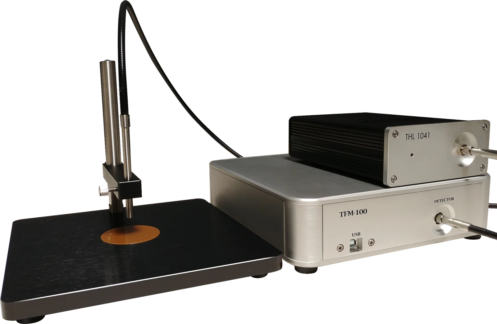
Easy recipe setup. Practical fitting workflow. Designed for straightforward operation without requiring optical-model expertise.
| Measurement method | Reflectance-based thin-film thickness measurement |
|---|---|
| Core workflow | Easy recipe setup. Practical fitting workflow. Designed for straightforward operation without requiring optical-model expertise. |
| Measurement workflows | Manual measurement, automated XY mapping, contact-style measurement, and external system integration |
| Available TFM systems | TFM-100, TFM-500, TFM-Contact, and TFM-Remote |
Select the first candidate system based on sample size, measurement workflow, and integration needs.
| Need / Workflow | Recommended Model | Sample Size / Handling | Best Fit |
|---|---|---|---|
| Manual sample checks | TFM-100 | Standard stage: wafers up to 4 inches. Optional manual stage: wafers up to 12 inches. Larger sample sizes can be discussed. | General-purpose lab use, sample testing, and recipe-based checks. |
| Automated XY mapping | TFM-500 | Supports wafers up to 12 inches and square samples up to 300 mm × 300 mm. A 370 mm × 470 mm stage option is available. | Multi-point mapping, uniformity review, and recipe-linked data storage. |
| Large / curved / installed coated parts | TFM-Contact | Various large or non-standard samples depending on probe access, surface shape, and fixture condition. | Coated parts that are difficult to place on a standard stage. |
| External control / integration | TFM-Remote | Sample size is defined by the customer-side stage, equipment, and optical setup. | Socket communication, remote operation, and automation workflows. |
Shared measurement specifications. Applicable settings depend on sample condition, film stack, optical contrast, and the measurement recipe.
| Measurement method | Reflectance-based thin-film thickness measurement |
|---|---|
| Typical measurement time | Typically 1–2 seconds for single-layer measurement |
| Spot size option | Approx. 40 µm with a 5× lens; approx. 20 µm with a 10× lens. The spot size depends on the selected lens and optical setup. |
| Supported layer count | Up to 3 layers in the current standard workflow. |
| Software | Lite included |
| PC / host connection | USB standard. Ethernet is available for remote-control or equipment-integration workflows. |
Note: Multilayer structures may require additional fitting time depending on layer count and recipe conditions.
Both systems can be installed on a standard laboratory table. The values below are recommended site provisions, not maximum power-consumption ratings.
| Model | Recommended Installation Space | Power Input | Recommended Available Power |
|---|---|---|---|
| TFM-100 | Approx. 1000 mm × 800 mm laboratory table | Single-phase AC 100–240 V, 50/60 Hz (220 V standard) | 200 W |
| TFM-500 | Approx. 1000 mm × 800 mm laboratory table | Single-phase AC 100–240 V, 50/60 Hz (220 V standard) | 500 W |
A SiO₂ reference sample was measured 10 times at the same point as an example repeatability check.
Actual results may vary depending on film stack, substrate, optical contrast, sample condition, and measurement recipe.
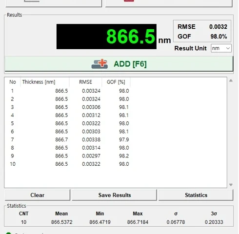
Representative model ranges are shown below. The usable range depends on the sample and recipe conditions.
| Model | Wavelength Range | Thickness Range* | Same-point Repeatability Reference |
|---|---|---|---|
| Standard | 350–1050 nm | 15 nm – 100 µm* | 500 nm SiO₂ reference sample, n=10 |
| NIR | 750–1100 nm | 1 µm – 500 µm* | 850 / 1000 nm SiO₂ reference sample, n=10 |
| XT | 1005–1080 nm | 100 µm – 2,000 µm* | 2000 nm SiO₂ or transparent reference film, n=10 |
* Depending on sample condition, film stack, substrate, optical contrast, and measurement recipe.
These examples show representative sample types and coating structures. Each application page provides additional measurement considerations.